Tonysa Smart Robot Car Kit, LM393 DIY Smart Tracking Car with Red LED Light, Mounting Instructions: Welding Circuit, Mechanical Assembly, Installing a Photocell, Debugging the Vehicle

£22.99

  • Make sure this fits by entering your model number.
  • PHOTORESISTOR DEVICE – This is a photoresistor, which can detect the strength of external light. The stronger the external light, the smaller the resistance of the photoresistor. The weaker the external light, the greater the resistance. When the red LED light is projected to the white area and the black racetrack, it is because of the reflectivity. The resistance value of the photoresistor will be significantly different, which is convenient for subsequent circuit control.
  • LM393 COMPARATOR INTEGRATED CIRCUIT – LM393 is a dual-channel voltage comparator integrated circuit, composed of two independent precision voltage comparators. Its function is to compare two input voltages and change the output voltage according to the level of the two input voltages. The output has two states: close to open or close to low level when pulled down. LM393 uses open collector output, so pull-up resistors must be added to output high level.
  • PRINCIPLE OF USE – The chip LM393 compares the size of the two photoresistors. When there is an imbalance (such as pressing a black track on one side), it immediately controls the motor on one side to stop, and the motor on the other side accelerates, so that the car corrects its direction and restores it to the correct direction. The whole process is a closed loop control, so it can be controlled quickly and sensitively.
  • INSTALLATION NOTES – This kit follows the principle of simple to complex. First, we make an intelligent tracking car controlled by a digital circuit. During the assembly process, we can not only be familiar with the mechanical principles, but also gradually learn: photoelectric sensor, voltage comparator, motor drive circuit And other related electronic knowledge.
  • The LM393 compares two photosensitive resistors and stops one motor if the resistance appears uneven other engine spins faster to get the car back in the right direction. The whole process is a closed-loop control, so it’s easy to steer.

In stock

— OR  —

— OR  —

  • International Express shipping available
  • 30 day easy returns
Guaranteed Safe Checkout

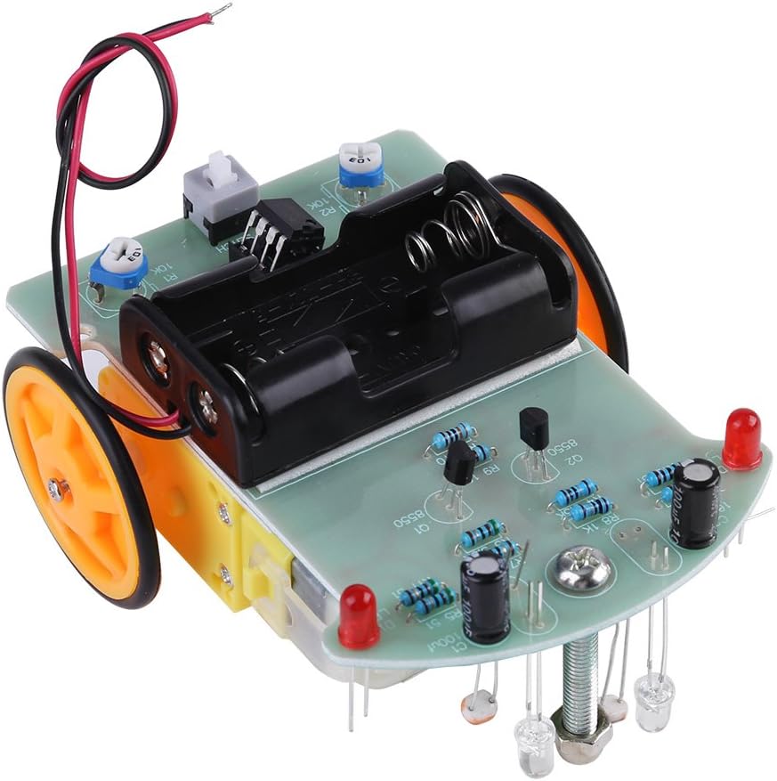
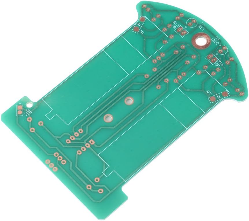
Assembly instructions: Step 1: welding circuit
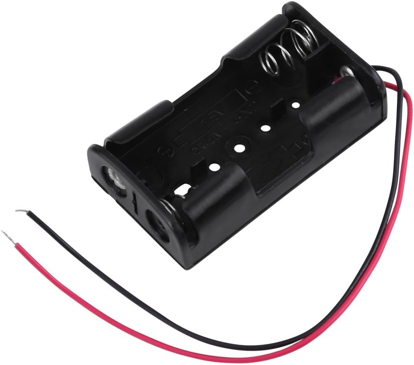
Electrowelding is easier, welding sequence according to the principle of component level from low to high, the first eight welding resistance, it is important to use multimeter to confirm the resistance correct. Step 2: Mechanical Assembly The red wire is connected to the positive 3V power supply, the same line grounding, excess wire can be used for motor cable. Step 3: Installing a photocell Photosensitive resistor and light emitting diodes (observe polarity) are mounted on the board upside down and the ground clearance is about 5 mm. Both the photosensitive resistor and the LEDs are 5 mm away. Finally, you can test the performance. Step 4: Debug the vehicle The right direction is along the universal wheel direction, if you push and hold the left photoresistor, the wheels on the right side of the car should be turned. Keep the right photoresistor pressed wheels on the left side of the car should be turned when the car is driving  back, can also replace the wiring of two motors, if one side normal and the other side high again, as long as you can replace the wiring on the back.
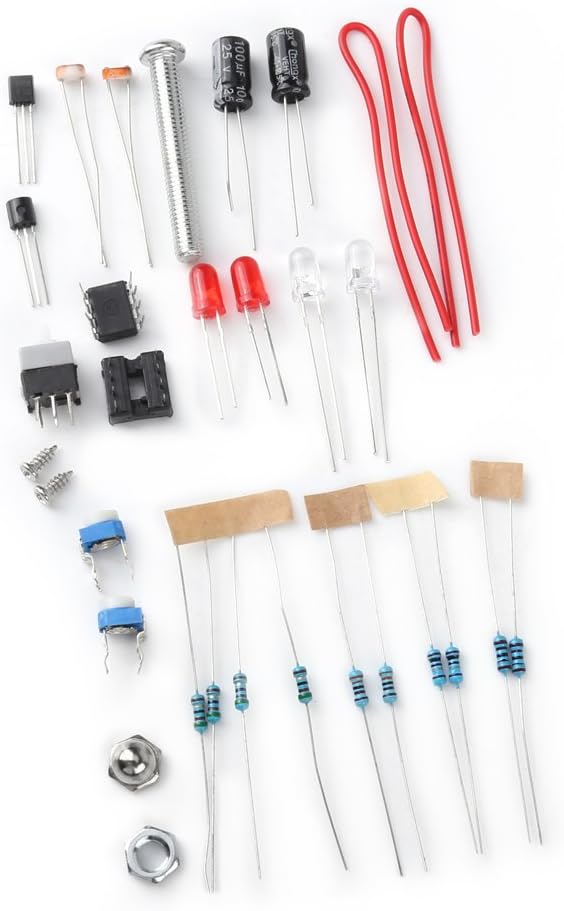
Package includes:
1 x Smart Car DIY Set (disassembled parts)

Additional information

Weight 0.11 kg
brand

Tonysa

dimensions

11 x 8 x 3 cm; 110 Grams